Introduction: New Reliability Challenges for MEMS Sensors
As a core cluster of the domestic MEMS sensor industry, Suzhou Nano City hosts more than 550 upstream and downstream enterprises and operates China’s first commercial 6-inch MEMS pilot platform. It has formed a complete industrial chain covering chip design, wafer manufacturing, packaging and testing. Driven by the rapid development of IoT, smart vehicles, aerospace and advanced industrial manufacturing, MEMS sensors are evolving toward higher integration, miniaturization and stricter operating conditions.
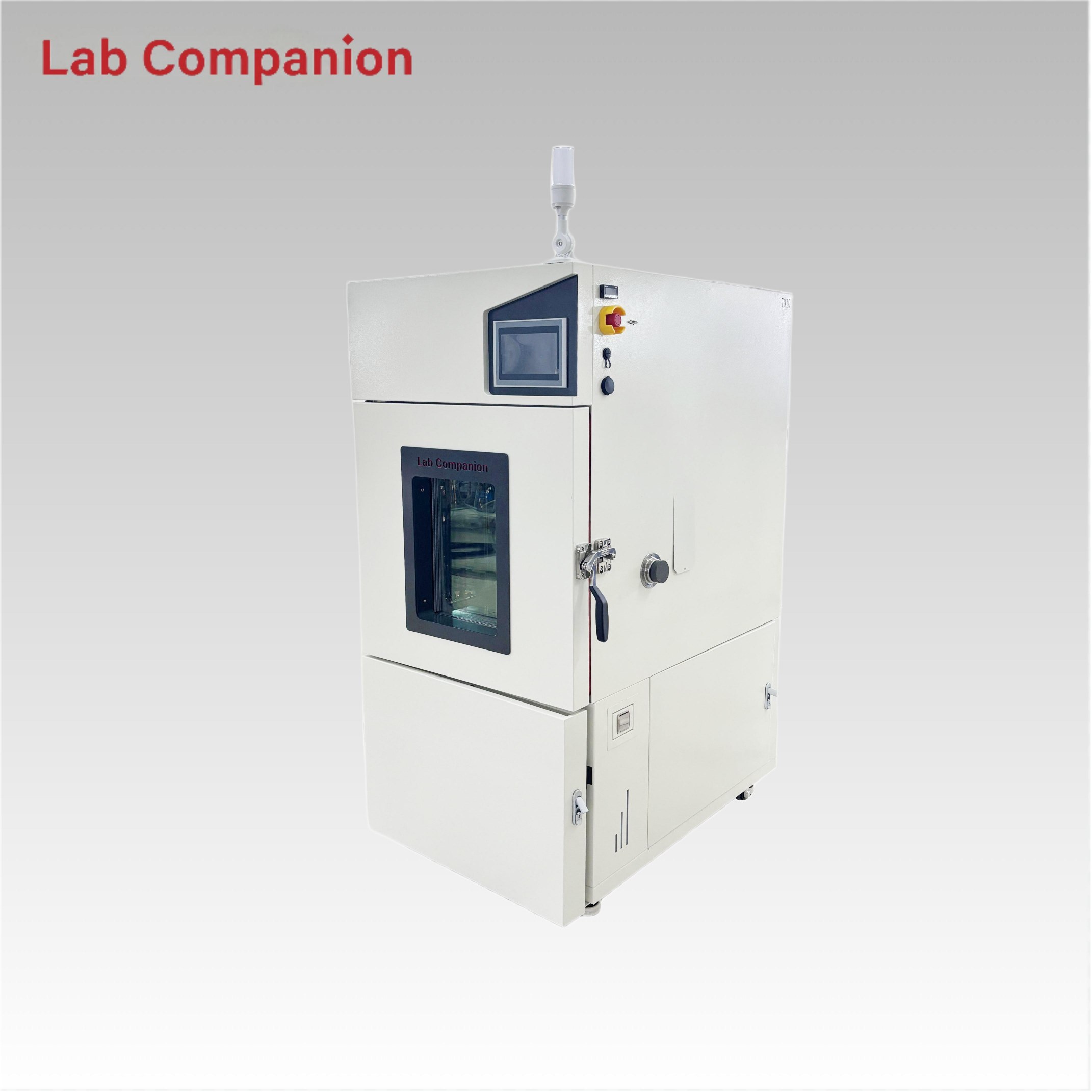
Against this backdrop, how to quickly and accurately identify latent defects in MEMS sensor design, material selection and production processes has become a universal industry challenge. To address this demand, Lab Companion has launched the HALT-type high-accelerated thermal cycling chamber. Featuring an ultra-high non-linear temperature change rate of up to 20℃/min, the equipment drastically shortens reliability testing cycles and exposes hidden early failures at the R&D stage, helping global MEMS manufacturers consolidate product quality.
1. High-Accelerated Thermal Cycling Testing: Break Traditional Limits for Extreme Reliability Verification
1.1 What is HALT Testing
HALT (Highly Accelerated Life Test) is an advanced reliability verification method applied in the electronic product R&D phase. Its core principle is maintaining consistent failure mechanisms, intensifying environmental stress, and compressing test duration. By applying extreme thermal cycling and temperature shock stress, HALT rapidly excites potential product weaknesses. Short-term accelerated test data can accurately predict product long-term reliability under standard operating conditions, serving as a critical validation solution before formal product finalization.
1.2 Why MEMS Sensors Require HALT Ultra-Fast Thermal Cycling
Integrated with micro-mechanical structures (cantilevers, thin films, resonant cavities) and precision signal processing circuits, MEMS sensors are far more sensitive to thermal stress and thermal expansion/contraction than conventional electronic components. Standard thermal cycling tests fail to effectively trigger latent failures. The main failure modes of MEMS sensors are summarized as follows:
• Microstructure Fatigue & Fracture: Repeated temperature fluctuations induce fatigue cracks on micro-cantilevers and resonant structures, leading to functional degradation over service time.
• Microstructure Adhesion & Friction Failure: Rapid thermal stress causes irreversible adhesion and stalling of micro-scale structures, undermining sensing accuracy.
• Packaging Thermal Stress Mismatch: Differential thermal expansion coefficients among chips, encapsulation materials and substrates cause stress concentration, resulting in packaging delamination and cracking.
• Interconnection & Solder Joint Failure: Extreme temperature shocks generate microcracks in internal solder joints and circuit interconnections, eventually causing poor contact or open circuits.
Conventional thermal cycling chambers only provide a temperature change rate of 1~3℃/min, requiring several hours for a single complete cycle. Such low stress intensity cannot efficiently expose micro latent defects. In contrast, Lab Companion high-accelerated thermal cycling chambers deliver a temperature change rate of over 10℃/min, enabling extreme high-low temperature switching in a short time. The intensified thermal stress effectively exposes design, material and process flaws, supporting iterative optimization before mass production and eliminating batch failure risks.
2. Core Technical Advantages of Lab Companion High-Accelerated Thermal Cycling Chambers
With years of expertise in environmental reliability testing equipment, Lab Companion independently developed the high-accelerated thermal cycling chamber series. It fully adapts to the full-cycle testing requirements of MEMS sensors from R&D verification to mass screening, solving traditional industry pain points including low efficiency, insufficient precision, contamination risks and incomplete data traceability.
2.1 Customizable Ultra-High Temperature Change Rate, 4X Higher Testing Efficiency
The equipment supports customizable linear and non-linear temperature change rates ranging from 5℃/min to 25℃/min, with top-tier models reaching 25℃/min — far exceeding conventional industry equipment. Taking the mainstream -40℃~125℃ thermal cycle test as an example, traditional devices take 2 hours per cycle, while Lab Companion chambers complete one cycle within 30 minutes. The solution achieves 4 to 5 times more cycles in the same testing period, efficiently stimulating latent failures such as microstructure fatigue and packaging stress defects. Users can freely switch between constant linear temperature change and segmented controllable non-linear acceleration modes according to diverse test standards.
2.2 Wide Temperature Range & High-Precision Control for Batch Test Consistency
Covering a full temperature range of -70℃ to +180℃, the chamber meets all-scenario MEMS testing demands including low-temperature cold start, normal operation, high-temperature storage and extreme temperature resistance. Equipped with a dual-air duct circulation system and distributed multi-point temperature sensors, it achieves a steady-state temperature uniformity of ≤±0.5℃ and dynamic uniformity better than ≤2.0℃ during rapid temperature changes. The balanced and precise thermal field supports synchronous batch testing of multiple MEMS sensors, eliminating data deviation caused by local temperature differences and ensuring highly reliable and consistent test results.
2.3 High-Cleanliness Chamber Design for Precision Chip Testing
MEMS bare dies and micro sensors are extremely sensitive to test environment cleanliness. Tiny dust and particle adhesion may cause test misjudgment or irreversible component damage. Lab Companion optimizes the chamber structure specifically for precision semiconductor testing scenarios. Adopting SUS304 mirror stainless steel inner tank and dead-angle-free arc welding technology, the inner wall minimizes particle adhesion and shedding risks. It perfectly adapts to high-precision scenarios such as wafer-level packaging and bare die testing, ensuring authentic test data and stable product yield.
2.4 Intelligent Programmable Control & Full-Cycle Data Traceability
Equipped with a self-developed high-definition programmable controller with bilingual (Chinese/English) interface, the device stores 100 groups of programs with 100 segments per group. It supports one-click calling of mainstream industry standards including JEDEC, MIL-STD and AEC-Q100, realizing unattended automatic testing. Integrated with Ethernet remote monitoring and USB data export functions, the chamber synchronizes real-time temperature curves, operating status and alarm information. All test data is automatically recorded, fully complying with data traceability requirements of IATF 16949 and ISO 17025 quality systems.
3. Typical Application Cases
Case 1: Extreme Thermal Stress Verification for MEMS Inertial Accelerometers
A professional IMU inertial sensor enterprise requires its vehicle-grade MEMS accelerometers to withstand harsh automotive operating conditions. At the product finalization stage, the enterprise adopted Lab Companion high-accelerated thermal cycling chamber with the test scheme: -55℃~+125℃ temperature range, 20℃/min non-linear temperature change rate, 10-minute dwell time per segment, 200 consecutive cycles.
The intensive alternating thermal stress quickly activated latent defects and exposed fatigue cracks on microstructure fixing anchors within 100 cycles. Based on failure analysis, the enterprise optimized the stress relief groove design of microstructures. Re-testing verified the complete elimination of similar failures, greatly improving the product’s thermal shock resistance and operational stability under extreme vehicle conditions.
Case 2: Temperature-Humidity Combined Accelerated Test for Smartphone MEMS Microphones
A professional acoustic module manufacturer encountered abnormal acoustic sensitivity attenuation of new-generation smartphone MEMS microphones under high-temperature and high-humidity environments. Traditional long-period humidity and temperature tests failed to quickly locate the root cause.
The enterprise adopted Lab Companion temperature-humidity composite high-accelerated thermal cycling chamber with combined thermal and humidity stress. The test parameters were set as15℃/min temperature change rate, 10%~95% RH humidity range and 50 test cycles. The accelerated test quickly confirmed that alternating rapid temperature and humidity fluctuations caused expansion and deformation of the waterproof and breathable membrane, resulting in sealing performance degradation. The manufacturer replaced the membrane with high humidity-resistant material, thoroughly solving the acoustic sensitivity failure and achieving rapid product iteration.
Case 3: Mass Stress Screening for Automotive-Grade MEMS Pressure Sensors
A leading automotive sensor supplier produces tire pressure monitoring MEMS pressure sensors that comply with strict AEC-Q100 automotive standards, requiring efficient batch defect screening during mass production.
The enterprise introduced Lab Companion high-accelerated thermal cycling chambers for mass production screening. The equipment supports simultaneous testing of 500 sensors per batch. With the test condition of -40℃~125℃ and 20℃/min ultra-fast temperature change, the original 24-hour screening cycle is shortened to 4 hours. The internal temperature uniformity is stably controlled within ±1.5℃, ensuring consistent thermal stress for all samples. This solution increases the defective product detection rate by 30% and reduces comprehensive screening costs by nearly 50%, balancing high screening accuracy and mass production efficiency.
4. Global Professional After-Sales & Technical Support
Lab Companion provides standardized global after-sales service and full-lifecycle technical support for overseas customers, ensuring stable and efficient equipment operation worldwide:
• Global Online Technical Support: Professional engineering teams provide 7×24-hour remote guidance, including equipment debugging, operation training, fault diagnosis and solution delivery.
• Standard Spare Parts Supply: Standardized spare parts and consumables are available globally to shorten equipment downtime and ensure continuous operation.
• Regular Calibration & Maintenance Guidance: Provide free annual remote equipment calibration, system inspection and maintenance guidance services.
• Customized Process Technical Training: Offer standardized operation documents and professional technical training, assisting customers in formulating test procedures compliant with JEDEC, MIL-STD, AEC-Q100 and other international standards.
• Extended Warranty Service: Optional extended warranty covers vacuum system maintenance, temperature sensor calibration and temperature control system inspection, guaranteeing long-term stable equipment performance.
5. Core Product Advantages Summary
• Industry-Leading Ultra-Fast Thermal Cycling: Customizable 5~25℃min temperature change rate, 4 times higher efficiency than traditional equipment, supporting high-frequency accelerated thermal cycle testing.
• High-Precision Full-Range Temperature Control: -70℃~180℃ ultra-wide temperature range, stable dynamic and static temperature uniformity, ensuring consistent batch test data.
• High-Cleanliness Precision Test Environment: Mirror stainless steel anti-pollution structure, suitable for high-standard testing of MEMS bare dies and packaged precision components.
• Standardized Global Data Traceability: Intelligent programmable control and remote monitoring system, fully compliant with international quality system certification requirements.
• Professional Global Technical Service: 24/7 online remote support and standardized after-sales system to minimize equipment operating risks and losses.
Conclusion
As foundational core components of intelligent terminals, smart vehicles, aerospace and industrial manufacturing, MEMS sensors determine the quality and stability of terminal products. High-accelerated thermal cycling testing is an essential method to excavate latent defects and improve the inherent reliability of MEMS devices from the source.
With advanced ultra-fast thermal cycling technology, high-precision temperature control, exclusive high-cleanliness design and standardized global service system, Lab Companion provides efficient, professional and compliant reliability testing solutions for global MEMS manufacturers. We help MEMS products improve extreme condition adaptability and overall reliability, empowering the high-quality development of global precision electronic component industries.
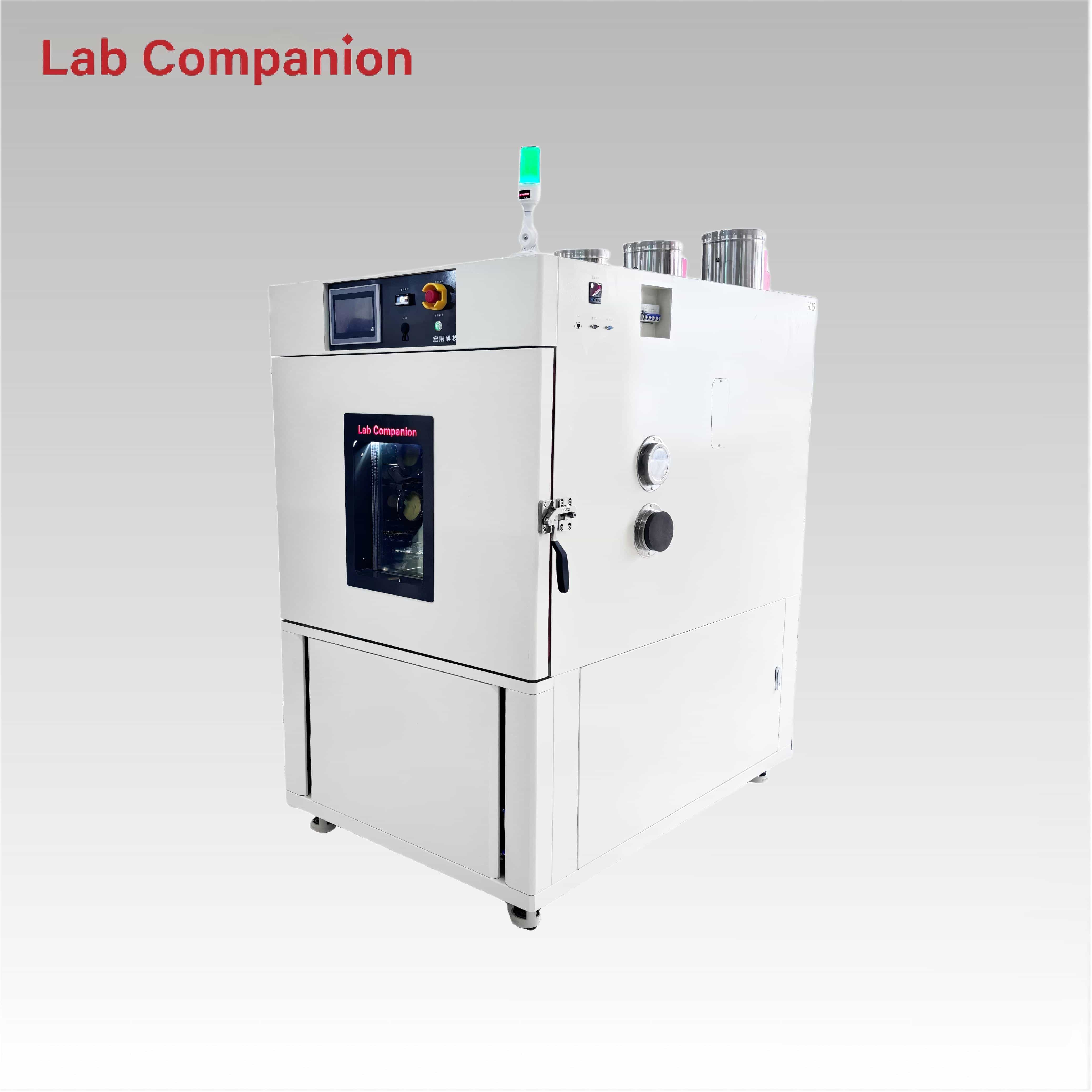
Lab Companion is deeply engaged in the semiconductor testing field. To address the core needs of precision testing in the industry, we have launched a semiconductor chip-specific high and low temperature humidity test chamber. With a high-cleanliness chamber structure and precise temperature and humidity control as its core highlights, the equipment is specially designed to provide full-scenario high-low temperature and humidity alternating environment testing for products such as chip wafers, bare chips, packaged devices, and semiconductor modules. It can fully meet the core needs of chip packaging reliability verification, aging testing, and environmental adaptability evaluation, providing stable, accurate, and clean test environment support for semiconductor product R&D, process optimization, and quality control.
I. Product Positioning: Specialized for Semiconductor Chips, Different from General-Purpose Test Equipment
This series of test chambers abandons the homogeneous design of general-purpose equipment and is fully optimized and upgraded around the precision characteristics of semiconductor chips. In terms of environmental cleanliness, temperature and humidity control accuracy, cabinet material selection, and anti-pollution structural design, it meets the strict requirements of chip testing. It can effectively avoid damage to precision chips caused by pollutants such as dust, impurities, and condensed water, and is widely applicable to core scenarios such as reliability assessment, failure analysis, and process verification before and after chip packaging. It is an exclusive and suitable equipment for semiconductor enterprises, packaging and testing factories, and research institutions to carry out chip environmental reliability testing.
II. High-Cleanliness Chamber Design: Building a Solid Line of Defense for Precision Chip Testing
The equipment adopts a high-cleanliness chamber structure, and the inner tank is made of high-quality mirror-finish 304/316 stainless steel. Its surface is smooth and dense, not easy to adhere to dust and impurities, and easy and efficient to clean and maintain. It reduces pollution to the chip surface, pins, and packaging structure from micro-particle dust at the source, ensuring that test samples are free from secondary damage.
The internal corners of the chamber adopt a full arc transition design, completely eliminating dead corners and greatly reducing the risk of dust accumulation. The air duct system has undergone professional dust-proof optimization, combined with a low-dust emission air supply mode, to continuously maintain a high-cleanliness state in the test space, perfectly matching the cleanliness requirements of chips, wafers, and packaged devices for the test environment. At the same time, the chamber adopts a tight sealing structure, which effectively blocks the entry of external air impurities and creates a stable, clean, and interference-free internal environment for chip testing.
III. Core Temperature and Humidity Parameters: Precisely Matching the Needs of Chip Packaging Reliability Testing
The temperature range of the equipment fully covers typical test scenarios such as chip low-temperature storage, high-temperature aging, and temperature-humidity cycling. It can be continuously adjusted over a wide range, with precise and stable control of temperature fluctuation and uniformity. It can provide uniform environmental stress for core components such as chip packaging layers, bonding wires, and substrate materials, ensuring that test results are consistent with actual application scenarios.
The humidity range can flexibly cover from low-humidity dry environment to high-temperature and high-humidity environment, accurately adapting to core chip packaging reliability projects such as accelerated humidity aging and Moisture Sensitivity Level (MSL) testing. The humidity control response is stable, effectively avoiding problems such as chip surface condensation, packaging colloid cracking, and pin oxidation caused by sudden humidity changes. It strictly complies with relevant semiconductor industry test standards, ensuring the standardization and reliability of the test process.
IV. Precise Temperature and Humidity Control: Ensuring Stable and Reliable Test Data
The control system is equipped with high-precision temperature and humidity sensors, combined with an intelligent PID adjustment algorithm, which can realize precise control and continuous stable maintenance of temperature and humidity. With small temperature and humidity fluctuations and excellent uniformity, it ensures that the same batch of chip samples is subjected to uniform stress during the test, and the test data has good repeatability and comparability, providing accurate data support for chip quality evaluation.
The equipment supports multi-segment program editing function. According to chip testing needs, it can customize the temperature and humidity rise and fall rate, holding time, and cycle times, perfectly adapting to the complex temperature and humidity alternating processes in chip packaging reliability testing. The program runs stably without parameter drift, which can meet the needs of long-term continuous aging testing and greatly improve test efficiency and accuracy.
V. Structure and Function Adaptation: Meeting Full-Scenario Chip Packaging Testing
The internal space of the chamber is compact and reasonably laid out, which can flexibly place test accessories such as chip trays, carriers, and packaging fixtures. It supports batch placement and testing of small-size chip samples, effectively improving test efficiency and adapting to the large-scale testing needs of enterprises.
The chamber is reserved with small lead holes and high-definition observation windows, which facilitate real-time monitoring of chip electrical parameters during the test, and can directly observe changes in chip appearance and status to detect test abnormalities in a timely manner. The internal air duct adopts a gentle air supply design, avoiding direct scouring of the chip surface by strong air flow, preventing chip displacement and damage, and is especially suitable for testing precision samples such as wafers and thin packaged chips.
VI. Multiple Safety Protections: Safeguarding the Operation of Chips and Equipment
In response to the precision and safety needs of chip testing, the equipment is equipped with a comprehensive safety protection mechanism, including over-temperature protection, humidity over-limit alarm, compressor overload protection, water shortage protection, leakage protection and other multiple functions. During long-term reliability tests, it can automatically monitor the equipment operation status in real time. Once an abnormality occurs, it will immediately shut down and alarm, effectively avoiding the impact of equipment failure on chip samples and ensuring the safety and continuity of the test process.
The refrigeration system adopts a low-vibration design, which greatly reduces vibration during equipment operation, avoids additional mechanical stress interference caused by vibration to chip bonding structures and micro-packaging components, further improves the stability of the test process, and protects the integrity of the chip structure.
VII. Typical Applications: Covering Full-Process Reliability Verification of Chip Packaging
The equipment can fully cover the full-process reliability testing of chip packaging. Before packaging, it can perform high-low temperature and humidity environment testing on wafers and substrate materials to verify the stability of materials under different environmental conditions and provide a basis for packaging process optimization. After packaging, through tests such as high-temperature and high-humidity aging, temperature cycling, and humidity storage, it can accurately evaluate the bonding reliability of packaging colloid, pads, and lead frames, and quickly identify potential failure problems such as delamination, cracking, and leakage.
At the same time, the equipment can be widely used in scenarios such as chip Moisture Sensitivity Level (MSL) verification, automotive chip environmental adaptability testing, consumer electronics chip reliability sampling inspection, and industrial chip weather resistance testing. It provides accurate and reliable data support for chip design optimization, packaging process improvement, and factory quality screening, helping enterprises improve product competitiveness.
VIII. Ingenious Manufacturing and Customized Technical Services
Lab Companion's semiconductor chip-specific high and low temperature humidity test chamber adopts precision sheet metal processing technology, with stable performance in chamber tightness and structural strength. The core control and refrigeration components are all selected from high-quality accessories suitable for semiconductor precision testing, ensuring stable and reliable long-term operation of the equipment and reducing later maintenance costs.
We provide customers with full-process technical services, including equipment installation and commissioning, operation training, and program setting guidance, helping customers get started quickly. At the same time, according to customers' chip size, packaging type, special test standards and scenario needs, we can make customized adjustments to the chamber volume, temperature and humidity range, cleanliness level, carrier interface, etc., fully meeting the exclusive testing needs of different semiconductor enterprises and providing one-stop precision testing solutions.
Industry Pain Point: Condensation Risks Threaten Precision Testing Safety
In high-end sectors such as semiconductors, optical components, and military-grade electronics, temperature and humidity testing is a critical process to verify product reliability and stability. However, condensation has long been a persistent industry challenge, especially under low-temperature high-humidity or alternating temperature-humidity conditions. Traditional test chambers are prone to forming condensation on inner chamber walls and sample surfaces, which can cause sample oxidation, performance degradation, or even short circuits and irreversible damage to precision components.
This not only leads to costly sample losses and interrupted testing schedules but also results in distorted test data, driving up R&D and testing costs for enterprises. Precision samples like microchips, high-precision optical lenses, and sensitive sensors are extremely vulnerable to condensation—even minor moisture buildup can render finished products scrapped, causing substantial financial losses and project delays. With 21 years of expertise in environmental test equipment, Lab Companion targets this core pain point with upgraded anti-condensation technology for its temperature & humidity test chambers, eliminating condensation risks at the source and securing full-process safety for precision sample testing.
Core Innovation: Triple Anti-Condensation System for Root-Cause Risk Elimination
Abandoning the traditional single anti-condensation design widely used in the industry, Lab Companion leverages its profound technical accumulation to develop an innovative "Pre-Heating + Anti-Condensation Coating + Optimized Airflow" triple closed-loop system. Tailored for the strict testing requirements of high-precision samples, this system achieves zero condensation under all operating conditions, thoroughly resolving the long-standing industry bottleneck with each upgrade directly addressing real-world testing pain points.
1. Intelligent Chamber Pre-Heating: Cut Off Condensation at the Source
The chamber is equipped with a self-developed intelligent pre-heating system that automatically raises the chamber temperature to 5-10℃ above the dew point before testing commences, while pre-conditioning samples to eliminate thermal temperature differences. This fundamentally prevents condensation caused by thermal shock in low-temperature high-humidity environments. During testing, a high-precision monitoring module tracks dew point temperature in real time, and AI algorithms dynamically adjust pre-heating power to maintain chamber temperature above the dew point consistently, blocking condensation formation at its origin.
2. Specialized Anti-Condensation Coating: Build a Physical Protective Barrier
Lab Companion applies a custom anti-condensation coating to all critical condensation-prone areas, including inner chamber liners, doors, and sample racks. This coating features excellent hydrophobic and anti-moisture properties, effectively preventing moisture adhesion. It also boasts high and low temperature resistance (-70℃ to +150℃) and corrosion resistance, ensuring long-term durability without peeling or degradation. Most importantly, it causes zero contamination to precision samples, balancing robust protection and operational safety.
3. Optimized Airflow Circulation: Suppress Moisture Accumulation
We have optimized the air duct design with a vortex guide duct and high-speed silent centrifugal fan, accelerating internal airflow circulation. This quickly disperses and evaporates trace moisture, preventing condensation buildup on samples and chamber walls. Uniform airflow also eliminates local low-temperature dead zones, further reducing condensation risks. Paired with an integrated boiler steam humidification system, it avoids the drawbacks of traditional water mist humidification, preventing secondary moisture damage to samples and maintaining a pure, stable testing environment.
Parameter Advantages: Precise Temperature & Humidity Control Boosts Anti-Condensation Performance
Complementing the core anti-condensation technology, Lab Companion test chambers deliver exceptional temperature and humidity control accuracy, creating a dual guarantee for reliable testing and enhanced anti-condensation performance, fully meeting the demands of precision sample testing.
• Wide Operating Range: Temperature coverage from -70℃ to +150℃, humidity control from 20%RH to 98%RH, adapting to extreme testing conditions and global industry standards;
• High Control Precision: Temperature accuracy ±0.3℃, humidity accuracy ±2%RH, temperature & humidity fluctuation ≤±0.3℃/±2%RH, locking in test parameters to avoid condensation from sudden temperature/humidity changes;
• Intelligent Dynamic Regulation: Equipped with high-precision dew point sensors that feed real-time data to a dual-PID cooperative control system, dynamically adjusting cooling, heating, humidification and dehumidification power to avoid mismatched "low temperature & high humidity" conditions;
• Flexible Alternation Speed: Adjustable temperature-humidity alternation rate from 0.1℃/min to 5℃/min, allowing customized gentle change curves based on sample characteristics to prevent condensation from rapid fluctuations.
Field Applications: Proven Performance Across High-End Industries
Lab Companion’s upgraded anti-condensation temperature & humidity test chambers have been widely deployed in semiconductor, optical, and military-grade electronics sectors worldwide, with proven performance validated by extensive real-world testing.
In thesemiconductor industry, leading chip manufacturers rely on Lab Companion HS Series chambers for reliability testing. Under harsh alternating conditions of -40℃ to +85℃, the chambers operate with zero condensation, boosting chip test pass rates and reducing costly sample scrap. In the optical industry, the chambers eliminate lens fogging and condensation, ensuring stable optical performance and accurate, repeatable test data for high-precision optical component R&D.
For military and defense applications, Lab Companion custom chambers meet strict military standards (GJB), providing a secure testing environment for electronic components and preventing condensation-related performance failures. Actual test data confirms: the chambers run continuously for 72 hours under extreme conditions (-40℃, 80%RH) with no condensation detected, far exceeding conventional industry performance benchmarks.
Craftsmanship & Innovation: Setting a New Standard for Precision Environmental Testing
While anti-condensation design may seem a detail, it directly impacts the safety of precision samples and the credibility of test data—two critical factors for enterprise R&D quality. For 21 years, Lab Companion has adhered to a customer-centric R&D philosophy, focusing on solving industry pain points through continuous technical refinement. Our triple anti-condensation system, paired with ultra-precise temperature and humidity control, completely eliminates condensation risks, protecting samples while improving testing efficiency and data reliability.
Moving forward, Lab Companion will continue to drive technological innovation and product iteration, upholding craftsmanship and professionalism to deliver safer, more accurate, and more reliable environmental testing solutions for global high-end industries. We are committed to empowering enterprises worldwide to enhance product reliability and core competitiveness through cutting-edge testing equipment.
In modern manufacturing—especially in high-reliability sectors such as electronics, automotive, and aerospace—product quality and service life depend not only on design and materials, but also on a rigorous, repeatable validation system. Thermal shock testing, one of the most stringent procedures in environmental reliability testing, serves as a core pillar of this system. It simulates the stress products endure under rapid, extreme temperature changes to reveal potential material defects, solder failures, and assembly issues.
Lab Companion deeply understands this logic. The company provides not just thermal shock test chambers, but complete solutions that help enterprises build standardized, reliable reliability verification capabilities. Through its profound understanding and practice of “standardized validation”—a fundamental industry need—Lab Companion has established a unique value position in the professional field.
I. Core Value: Beyond Equipment, Building Trustworthy Validation Capabilities
For any quality-focused enterprise, the ultimate goal of investing in a thermal shock test chamber is to obtain credible, traceable, and standard-compliant test data. Such data supports design improvement, ensures mass production consistency, and acts as a “technical passport” for customer approval and market access.
Lab Companion’s philosophy centers on how to guarantee the authority and validity of test data.
1. Standard Compliance and Repeatability of Test Conditions
Equipment must accurately reproduce conditions defined by standards including GB/T 2423.22, IEC 60068-2-14, and automotive standards such as AEC-Q100. These standards impose strict requirements on temperature transition time, dwell time, temperature extremes, and recovery time.
Lab Companion’s equipment is designed to meet these standards from the outset. Its two-zone fast mechanical switching (<10 seconds) and three-zone precision airflow control minimize variables, ensuring consistent, traceable conditions for every test.
2. Long-Term Stability for Consistent Data Over Time
Reliability testing often involves long-term, repeated cycling. While performance during acceptance is important, stability over hundreds or thousands of harsh thermal shock cycles is critical.
Lab Companion enhances structural durability, uses long-life core components (compressors, sensors), and conducts rigorous factory aging tests to reduce performance degradation. This ensures quality data remains comparable and reliable for months or even years.
3. Auditable Test Processes and Data Chains
In modern supply chains, test reports must themselves be verifiable. Lab Companion’s intelligent control system acts as a guardian of data integrity, recording temperature profiles, transition timestamps, operation logs, and equipment status in tamper-proof electronic records.
This is essential for enterprises pursuing ISO/IEC 17025 accreditation or providing original test evidence to clients.
II. Product Design Engineered for Standardized Validation
Every detail of the Lab Companion thermal shock test chamber is built to support standardized verification.
Clear performance boundaries: Specifications include not only no-load performance but also performance curves under real load conditions, helping users match equipment to actual samples.
Reliability in critical details: Optimized airflow ensures temperature uniformity under load; redundant safety interlocks prevent operational errors; convenient calibration ports support traceable third-party metrology.
Modularity and scalability: Flexible electrical and communication interfaces (including LIMS integration) support future upgrades and custom fixtures, protecting long-term investment.
III. Solving Industry Pain Points: From “Having Equipment” to “Having Capability”
Many enterprises face common challenges when adopting thermal shock testing. Lab Companion delivers value beyond hardware:
1. “Multiple standards exist—how to select and implement?”
The technical team assists in interpreting standards based on industry (consumer electronics, automotive, military) and product characteristics, providing compliant test configurations.
2. “Inconsistent results: equipment or sample?”
Support goes beyond troubleshooting. The team helps analyze test methods, sample mounting, and sensor placement, turning equipment into a reliable diagnostic tool.
3. “How to turn data into quality improvement?”
Standard, reliable test data establishes a quality baseline. By comparing results across designs and batches, enterprises quantify improvements driven by reliability testing.
IV. Selection Guidance: Start with the End in Mind
We recommend a structured approach to selecting a thermal shock chamber:
Clarify verification objectives: certification, R&D screening, or quality monitoring? This defines performance rigor.
Define test load: sample size, weight, material, heat capacity, and operating status. This determines two-zone / three-zone type and chamber size.
Evaluate process capability (Cpk): Focus on long-term stability, not just nominal specs. Inquire about drift data and calibration cycles.
Assess supplier empowerment: Choose a partner that explains standard compliance, data reliability, and provides full lifecycle support.
Conclusion
As manufacturing competition increasingly focuses on quality and reliability, a high-performance, stable thermal shock test chamber becomes a cornerstone of an enterprise’s quality defense.
Lab Companion delivers more than standard-compliant hardware. By partnering with customers to build standardized, trustworthy validation processes, it helps transform abstract “reliability” into measurable, controllable, and improvable engineering practice.
Choosing Lab Companion means choosing a long-term partner dedicated to empowering your product quality upgrade through professional equipment and expertise.
With the rapid development of electronics, new energy, aerospace and other industries, conventional standard fast temperature chambers can no longer meet the personalized testing needs of some enterprises, making non-standard customization an increasingly popular choice. However, many enterprises fall into the misunderstanding of "blind customization" when making customizations, believing that all needs can be customized or over-customizing, which leads to doubled customization costs, extended cycles, and even some customization needs that are meaningless and become "false needs".
With 21 years of experience in non-standard customization and thousands of customized cases completed, Lab Companion combines practical experience to clarify the core customizable dimensions of fast temperature chambers, analyze common "false needs", help enterprises accurately sort out customization needs, avoid over-customization, and achieve "customized adaptation and controllable costs".
I. Core Customizable Dimensions of Fast Temperature Chambers (Achievable)
Combined with industry needs and technical feasibility, the customizable dimensions of fast temperature chambers are mainly divided into 4 categories, all of which can be accurately implemented:
1. Temperature Range Customization: The temperature range of conventional equipment is -70℃~+180℃. According to enterprise needs, we can customize a lower temperature (minimum -100℃) or a higher temperature (maximum +250℃) to adapt to harsh testing scenarios such as aerospace and military industry. For example, Lab Companion customized a fast temperature chamber for a military enterprise with a temperature range of -78℃~+150℃, which meets the GJB 150.5A military standard.
2. Volume and Size Customization: The conventional volumes are 150L, 225L, 400L, 600L and 1000L. According to the size and batch of test products, we can customize small volumes (minimum 50L) or large volumes (maximum over 10000L) to adapt to the testing of products of different sizes such as small chips, large automotive battery packs and motors. For example, Lab Companion customized a large fast temperature chamber with a volume of 5000L for a new energy enterprise, which can test multiple automotive battery packs at the same time, greatly improving testing efficiency.
3. Temperature Change Rate Customization: The conventional temperature change rate is 5-20℃/min. According to testing standards, we can customize a higher temperature change rate (maximum 30℃/min) or more precise temperature change rate control to adapt to the dynamic temperature testing needs of special products. For example, the equipment customized by Lab Companion for a semiconductor enterprise can realize stepless control of temperature change rate from 1-20℃/min, accurately matching the needs of different stages of chip testing.
4. Special Function Customization: According to industry testing needs, we can customize special functions such as nitrogen replacement, probe station interface, high heat load adaptation, remote monitoring upgrade and automatic data analysis to adapt to personalized testing scenarios in semiconductor, AI, military and other industries. For example, for semiconductor chip testing, the nitrogen replacement function is customized to prevent chip oxidation; for AI server testing, the high heat load adaptation function is customized, with a heat load capacity of up to 60kW, ensuring stable testing.
II. Common "False Customization Needs" (To Avoid)
The so-called "false needs" refer to needs that can be met through adjustment or simple modification of conventional equipment without customization. If such needs are blindly customized, they will increase customization costs and cycles, and have no practical significance. Common false needs are as follows:
1. Blind Upgrade of Temperature Change Rate: Many enterprises think that the higher the temperature change rate, the better, and blindly require customization of a high rate of 30℃/min, but their own testing standards only require 10℃/min. Customizing a high rate not only increases the cost by more than 30%, but also doubles the energy consumption in the later stage, which cannot play a role in actual use.
2. Excessive Volume Enlargement: Some enterprises blindly require customization of large-volume equipment for fear that the test products cannot be accommodated, but ignore their own test batch and laboratory space, resulting in excessive equipment volume, waste of energy consumption, excessive space occupation, and a significant increase in procurement costs. For example, if only small electronic components are tested, the conventional 225L equipment can meet the needs, and there is no need to customize large equipment above 600L.
3. Redundant Customization of Special Functions: Some enterprises blindly pursue "complete functions" and customize various special functions such as nitrogen replacement and probe station interface, but their own testing scenarios do not need them. For example, conventional electronic component testing does not require customization of nitrogen replacement function. Such redundant customization will increase the cost by 10%-20% and make later maintenance complicated.
III. Lab Companion's Non-Standard Customization Advantages
In the non-standard customization service, Lab Companion will first sort out the testing needs for enterprises, distinguish between "necessary customization needs" and "false needs", and provide reasonable customization schemes combined with the enterprise's testing standards, product characteristics and budget, so as to avoid over-customization. At the same time, Lab Companion has a professional customized R&D team with a short customization cycle (20-30 days for conventional customization and 45-60 days for complex customization), and communicates with enterprises throughout the customization process to ensure that the customized equipment accurately adapts to the needs, while controlling the customization cost and cycle.
IV. Core Principle of Non-Standard Customization
The core of non-standard customization is "adapting to needs and focusing on practicality", rather than blindly pursuing "completeness and high-end". When customizing fast temperature chambers, enterprises need to rationally put forward customization needs based on their own testing needs, avoid "false needs", and choose manufacturers with strong customization capabilities and rich experience, such as Lab Companion, to achieve "customized adaptation, controllable costs and improved efficiency", so that customized equipment can truly empower testing work.
In environmental simulation testing, Rapid Temperature Change Chambers and Thermal Shock Chambers are both critical for verifying product reliability under temperature stress. However, many customers choose the wrong equipment due to unclear working principles and application scenarios:
• Simulating natural gradual temperature changes with a thermal shock chamber → test results do not reflect real working conditions.
• Testing resistance to instantaneous temperature shock with a rapid temperature change chamber → fails to meet test requirements.
Wrong selection wastes investment, delays R&D, and weakens market competitiveness.
Based on more than 20 years of industry experience, LabCompanion® explains the core differences between these two chambers to help you select the right equipment for your application.
I. Core Principle Differences
1. Rapid Temperature Change Chamber
Single-chamber design · Continuous & gradual temperature change
• The entire test is performed in one single test space.
• Heating and cooling systems work together to provide smooth, continuous, adjustable temperature ramping.
• Temperature change rate: 5–20°C/min (higher rates available upon request).
• LabCompanion® advantage: Binary cascade refrigeration, high-efficiency heating, and dual PID + AI intelligent control for stable, precise ramping without sudden fluctuations.
• Simulates real-world natural temperature cycles.
2. Thermal Shock Chamber
Multi-chamber design · Instant temperature switching
• Typically 3 independent zones (hot chamber, cold chamber, test area); 2-zone models also available.
• Test samples are rapidly transferred between hot and cold environments with no gradual ramping.
• Temperature shock speed: > 5°C/s (up to 10°C/s for high-performance models).
• LabCompanion® advantage: Independent heating & cooling systems, fast-acting valves, and airflow guidance for extreme temperature shock.
• Temperature range:
○ Hot zone: +60°C to +200°C
○ Cold zone: -70°C to 0°C (down to -196°C with liquid nitrogen)
II. Key Parameters & Temperature Characteristics
Rapid Temperature Change Chamber
• Focus parameters: Ramp rate, temperature accuracy ±0.1–±0.5°C, uniformity ≤ ±2°C
• Standard range: -70°C to 180°C (customizable to -220°C)
• Temperature behavior: Continuous, smooth, gradual
• Strength: High precision, uniform temperature field
Thermal Shock Chamber
• Focus parameters: Shock temperature range-196°C to +200°C, shock speed, recovery time
• Temperature behavior: Instant, extreme, non‑gradual change
• Strength: Ultra-fast shock, high stability for harsh testing
III. Application & Selection Guide
Choose Rapid Temperature Change Chamber if:
• You need to simulate natural daily/seasonal temperature cycles.
• You want to evaluate long-term reliability under repeated gradual temperature changes.
• Industries:
○ Automotive electronics & components
○ Consumer electronics
○ Semiconductors & PCBs
○ General electronic reliability testing
Choose Thermal Shock Chamber if:
• You need to simulate extreme, instantaneous temperature swings.
• You want to expose material weaknesses, cracks, or failures quickly.
• Industries:
○ Aerospace
○ Military & defense
○ High-performance alloys
○ Semiconductor packaging
○ Components used in extreme environments
IV. LabCompanion® Solutions & Services
1. Dual-Mode Customization
For customers needing both temperature cycling AND thermal shock, LabCompanion® provides customized dual-mode systems that support: Single-chamber rapid temperature changeDual-chamber thermal shock in one integrated unit, reducing cost and space.
2. Compliance & Quality
All LabCompanion® chambers meet international and national standards, providing reliable alternatives to imported equipment at a competitive cost.
3. Global Service Support
• Professional one-on-one application & selection support
• Comprehensive after-sales guidance service (2-hour response) to assist with installation, calibration, maintenance, and training remotely
• Full lifecycle support: professional guidance for installation, calibration, maintenance, and technical training
V. Summary – How to Choose
• Simulate real natural temperature changes → Rapid Temperature Change Chamber
• Test resistance to extreme instant temperature shock → Thermal Shock Chamber
LabCompanion® provides professional, reliable environmental test solutions to support your product R&D and quality assurance.
In environmental reliability testing, temperature test chambers and thermal shock test chambers are two core instruments designed to verify the performance stability of products under extreme temperature conditions. However, they differ significantly in temperature change mode, test objectives, core parameters, and application scenarios.
As a national high-tech enterprise with over 20 years of industry experience, Lab Companion. leverages mature R&D and manufacturing capabilities to provide comprehensive environmental testing solutions across multiple industries. This article compares the two types of chambers from three dimensions: core parameters, structural design, and application scenarios, and offers targeted selection advice based on Lab Companion’s product features to help enterprises select the optimal testing equipment.
1. Core Performance Parameters: Fundamental Difference Between Gradual & Sudden Temperature Change
The core distinction between the two instruments lies in their design positioning for temperature change modes:
• Temperature Test Chamber: Gradual temperature change, steady-state constant temperature
• Thermal Shock Test Chamber: Sudden temperature shock, rapid switching
1.1 Temperature Range & Temperature Change Rate
Temperature Test Chamber
• Temperature range: Standard -70℃ ~ 150℃; customizable up to -100℃ ~ 200℃
• Temperature change feature: Average gradual rate; standard heating ≈ 5℃/min, cooling ≈ 3℃/min
• Rapid temperature change model: Equipped with dual-stage compression + eco-friendly refrigerant, with a rate of up to 20℃/min, suitable for accelerated aging tests
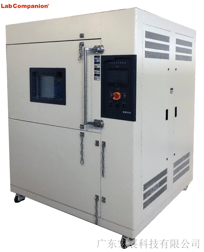
Lab Companion Thermal Shock Test Chamber (TS Series)
• Temperature range: Standard -65℃ ~ 150℃; customizable to -80℃ ~ 200℃
• Core advantage: Instant temperature switching (instead of average rate)
• Two-zone (TS2): Temperature transfer time ≤ 30 seconds, ≤ 10 seconds for small samples
• Three-zone (TS3): Equipped with pre-heating & pre-cooling chamber design, featuring higher switching efficiency and more stable shock performance
1.2 Temperature Uniformity & Fluctuation
Temperature Test Chamber
• Focuses on the accuracy of steady-state temperature field
• No-load uniformity ≤ ±2℃ (up to ±1.5℃)
• Fluctuation ≤ ±0.5℃; precision model up to ±0.3℃
• Ideal for long-term constant temperature and cyclic gradual change tests
Thermal Shock Test Chamber
• Slightly wider stability tolerance due to frequent temperature switching
• Uniformity ≤ ±1.5℃
• Fluctuation: Three-zone ≤ ±0.3℃, Two-zone ≤ ±0.5℃
• Equipped with dedicated PID algorithm for dynamic temperature control, reducing overshoot and ensuring consistent shock accuracy
1.3 Core Parameter Comparison (Compact Version)
Parameter
Temperature Test Chamber
Thermal Shock Test Chamber (TS Series)
Temperature Range
Standard: -70℃ ~ 150℃;Custom: -100℃ ~ 200℃
Standard: -65℃ ~ 150℃;Custom: -80℃ ~ 200℃
Temperature Change
Gradual change, average 0.5~20℃/min
Sudden thermal shock, transfer ≤ 30s, recovery ≤ 5min
Uniformity / Fluctuation
Uniformity ≤ ±2℃ (±1.5℃), Fluctuation ≤ ±0.5℃
Uniformity ≤ ±1.5℃, Fluctuation ±0.3~±0.5℃
Cycle Programming
1~999 programmable cycles, multi-segment curves
1~999 adjustable cycles, supports continuous shock
2. Structural & System Design: Differentiated Architectures for Diverse Temperature Change Needs
2.1 Refrigeration System
Temperature Test Chamber
• Above -40℃: Single-stage compression refrigeration
• Low-temperature range: Dual-stage cascade system with imported brand compressors
• Full-capillary automatic load regulation, ensuring precise temperature control and over 30% lower energy consumption
Thermal Shock Test Chamber (TS Series)
• Binary cascade air-cooled refrigeration system (high-temperature + low-temperature circuits)
• Adopts eco-friendly refrigerants R23/R404A, compliant with environmental protection regulations
• Mean Time Between Failures (MTBF) > 8,000 hours
2.2 Chamber & Air Duct Design
Temperature Test Chamber
• Single-chamber structure, inner tank made of SUS304 mirror stainless steel
• High-density polyurethane foam + silicone rubber seal, achieving superior thermal insulation performance
• 3D circulating air duct (top supply, bottom return), ensuring uniform temperature field and high versatility
Thermal Shock Test Chamber
• Two-zone (TS2): Equipped with pneumatic basket for direct sample transfer between hot and cold chambers; compact structure and cost-effective
• Three-zone (TS3): Additional intermediate transition chamber to reduce hot-cold air interference, lower temperature loss and improve precision – ideal for precision samples
• Inner tank: SUS304 stainless steel; outer cabinet: anti-corrosion electrolytic plate with paint finish
2.3 Control System
Temperature Test Chamber
• Siemens PLC + 7-inch touchscreen
• 100+ programs storage, 99 segments per program
• Segmented PID + AI adaptive control, with 99.5% data repeatability
Thermal Shock Test Chamber
• Youyi E-560/600 or 7.5-inch color touchscreen
• 96 program storage slots, embedded PLC for dynamic load adaptation
• Standard RS-232/RS485 interface, supporting data export and remote monitoring
3. Test Functions & Application Scenarios: Precise Matching for Industry Testing Needs
3.1 Temperature Test Chamber: General-Purpose Gradual Temperature Change Testing
Core Purpose
Simulate gradual temperature environments such as diurnal temperature variation and seasonal alternation; support constant temperature, high-low temperature cycling, and multi-segment programmable testing.
Applicable Industries
• Standard model: Consumer electronics, home appliances, plastics, hardware, and other general temperature resistance verification
• Rapid temperature change model: New energy, automotive electronics, 5G communications, aerospace, and other accelerated aging & cyclic reliability tests
• Customizable: Explosion-proof, anti-corrosion, large-volume, low-humidity, and other special working conditions
3.2 Thermal Shock Test Chamber: Severe Sudden Temperature Change Testing
Core Purpose
Simulate instantaneous extreme temperature changes during transportation or operation; evaluate cracking, failure, and performance drift caused by thermal expansion and contraction of materials.
Applicable Industries
• Aerospace: Instant temperature change between high altitude and ground
• Automotive components: Shock from cold start to high-temperature driving
• Harsh reliability verification for electronics, metals, rubber, military, and other fields
• Two-zone: Suitable for scenarios with limited budget and general thermal shock requirements
• Three-zone: Suitable for high-standard requirements (ISO, GB/T, etc.) in precision electronics, military, and other fields
4. Core Selection Logic & Precautions
Selection Priority: Demand Matching > Blind High Configuration
By Temperature Change Mode
• Gradual change & long-term steady state → Choose temperature test chamber
• Instant sudden change & thermal shock → Choose thermal shock test chamber
By Industry & Standards
• Consumer electronics, home appliances, basic materials → Temperature test chamber for better cost performance
• New energy, automotive, aerospace, military → Rapid temperature change chamber or three-zone thermal shock chamber
By Budget & Maintenance
• Temperature test chamber: Simple structure, low procurement and maintenance costs
• Thermal shock test chamber: Multi-chamber + cascade refrigeration, with slightly higher cost and maintenance requirements
Safety & After-Sales (Lab Companion Standard)
• 12 safety protection functions: Over-temperature, overload, compressor overheating, water shortage, fan failure, etc.
• National after-sales service network, providing regular maintenance guidance to ensure long-term stable operation
Conclusion
Temperature test chambers and thermal shock test chambers are not substitutes but complementary for different scenarios:
• Temperature Test Chamber: General-purpose, gradual change, steady state, cost-effective
• Thermal Shock Test Chamber: Severe, sudden change, shock-resistant, high-reliability verification
By combining product characteristics, industry standards, and test objectives with <span
With the rapid development of the new energy vehicle industry, the safety and reliability of power batteries directly determine vehicle quality. High-low temperature testing is a key link, which must strictly comply with standards such as IEC 62133 and GB/T 31484. Currently, enterprises generally face three major pain points: thermal runaway risks, difficulty in standard compliance, and insufficient non-standard adaptation. With over 20 years of experience in environmental testing equipment, Guangdong Labcompanion has launched a dedicated explosion-proof high-low temperature test chamber for new energy, providing one-stop solutions with customized and compliant advantages.
I. Core Pain Points of Power Battery High-Low Temperature Testing
High-low temperature testing is the "lifeline" of power battery R&D and mass production, with core pain points focusing on three aspects:
l High thermal runaway risks: Swelling and fire are likely during testing; traditional equipment lacks targeted explosion-proof design, easily causing safety accidents and losses.
l Difficult compliance: Insufficient temperature control accuracy and incomplete data recording of traditional equipment lead to certification rework, making it hard for SMEs to enter the mainstream market.
l Poor non-standard adaptation: Long customization cycle (3-6 months) and high cost fail to match R&D schedules and diverse needs.
II. Labcompanion’s Customized Solutions
Targeting the pain points, Labcompanion solves the dilemmas from three core dimensions based on the needs of leading enterprises:
l Full-dimensional explosion protection: Real-time battery monitoring, passive protection, and inert gas replacement to eliminate safety hazards.
l Compliance guarantee: Temperature control accuracy ±0.3℃, uniformity ≤±0.5℃, traceable data, and professional certification guidance.
l Rapid customization: Volume 36L~1000L, customization cycle shortened to 1-3 months, supporting function expansion and intelligent operation.
III. Benchmark Case & Selection Suggestions
Labcompanion’s explosion-proof test chamber helped BYD shorten the R&D cycle of solid-state batteries by 20%, successfully pass IEC 62133 certification, and achieve bulk procurement.
Key selection points: Prioritize manufacturers with complete explosion-proof qualifications, compliance with standards, and strong customization and after-sales capabilities (Labcompanion has service centers in 12 cities nationwide, with 2-hour response, 48-hour on-site support, and 3-year warranty).
IV. Conclusion
Through technological innovation, Labcompanion solves key testing pain points of power batteries, gaining trust from leading enterprises. It will continue to deepen its layout to help the high-quality development of the new energy industry.
High and low temperature test chambers are the "invisible guardians" in industrial production and scientific research innovation. They can simulate extreme environments to test product reliability, from small mobile phone chips to large automotive components. Starting from basic cognition, core parameters, industry trends, and usage misunderstandings, this article interprets their value and Labcompanion's practice.
I. Basic Cognition: The "Environmental Tester" for Product Quality
High and low temperature test chambers simulate natural environments by artificially regulating temperature, exposing performance defects of products under extreme temperature conditions in advance, helping enterprises optimize designs before mass production and avoid recall risks. Their applications cover electronic and electrical, medical, automotive, scientific research institutions and other fields, with test objects including PCB boards, monitors, automotive sensors, etc.
II. Key Parameters: Core Indicators for Selecting the Right Equipment
Core parameters determine equipment adaptability, with key indicators as follows:
1. Temperature control accuracy (deviation ±0.1℃~±0.5℃, high precision suitable for scientific research/high-end manufacturing);
2. Temperature uniformity (high-quality equipment ≤±2℃, high-end models ≤±1℃);
3. . Temperature range (conventional -40℃~150℃, special scenarios up to -80℃~200℃+);
4. Temperature change rate (10℃/min+ rapid temperature change can shorten test cycles);
5. Volume (from dozens of liters of desktop to dozens of cubic meters of walk-in, suitable for different scenarios).
III. Industry Trends: Green, Intelligent and Customized as the Mainstream
With industry upgrading, three major trends highlight competitiveness: 1. Green energy saving: Adopting environmentally friendly refrigerants, optimized refrigeration cycle and other technologies, energy consumption can be reduced by 20%+; 2. Intelligent interconnection: Realizing remote monitoring, automatic data collection and analysis, suitable for digital management; 3. Customization: Providing personalized designs for medical sterility, new energy explosion-proof and other needs.
IV. Usage Misunderstandings: Four Major Pitfalls to Avoid
1. The temperature change rate is not the faster the better; it needs to match product characteristics and test standards;
2. Uniformity cannot be ignored; uneven temperature field will lead to result deviation; 3. Regular maintenance is indispensable, otherwise it will affect accuracy and increase energy consumption;
4. The load capacity should not exceed 30% of the chamber volume to avoid damaging temperature field uniformity.
V. Labcompanion: A Quality Practitioner Following Trends
Labcompanion focuses on R&D and practices the three major trends: In terms of green energy saving, it adopts environmentally friendly refrigerant R449A and cascade refrigeration + CO₂ working fluid technology, reducing energy consumption by 28%~38% and obtaining provincial energy-saving certification; In terms of intelligence, it is equipped with an AI intelligent control system, supporting remote monitoring and automatic data analysis, with preset 200+ test programs; In terms of customization, it provides customized temperature range, chamber structure, etc., covering the needs of various industries. Its equipment has excellent core parameters: temperature control accuracy ±0.1℃~±0.3℃, uniformity ≤±1.5℃, temperature range -80℃~200℃. Relying on 20 years of experience, it provides full-process services from demand analysis to maintenance.
High and low temperature test chambers bear the responsibility of ensuring product quality. Accurately understanding core information can help select equipment and avoid pitfalls. Labcompanion creates trend-compliant equipment through technological innovation, providing support for quality upgrading in various industries.
1. Electronics Industry (Chips, Components)
Q: Does inner tank size and material affect testing for small precision components?
A: Select 36-100L small-volume inner tank (reduces temperature fluctuation); prioritize 304 stainless steel (corrosion-resistant, uniform heat conduction). Confirm multi-point temperature collection (≥8 points) support. Hongzhan offers customizable zoned temperature measurement, synchronous data upload, and chip batch testing compatibility.
Q: Will the refrigeration system degrade after 72 hours of continuous high-intensity testing?
A: Focus on refrigeration configuration: choose two-stage cascade refrigeration (more stable than single-stage) with imported compressors (Danfoss/Coppa). Hongzhan equipment features MTBF of 20,000 hours, no continuous operation attenuation, and overload protection.
2. New Energy Industry (Batteries, Charging Piles)
Q: For battery testing with explosion-proof requirements, how to judge equipment explosion-proof rating and safety design?
A: Must comply with ATEX explosion-proof certification. Inner tank equipped with explosion-proof pressure relief valve and inert gas inlet; circuit adopts flameproof design. Hongzhan customizes Ex d IIB T4 explosion-proof test chambers, suitable for lithium battery thermal runaway simulation.
Q: Can equipment heating/cooling rate meet large-capacity battery pack testing? Is energy consumption high?
A: Select custom models ≥1000L with temperature change rate ≥10℃/min; adopt CO₂ natural refrigerant system (38% lower energy consumption than traditional). Hongzhan optimizes refrigeration circuits for new energy, maintaining stable rates under heavy loads and saving over 10,000 yuan in annual electricity costs.
3. Aerospace Industry (Components, Aircraft Assemblies)
Q: Can temperature uniformity meet standards in extreme temperature ranges (-80℃ to 200℃)?
A: Select equipment with "PID self-tuning + fuzzy control"; inner tank adopts honeycomb air duct design (reduces temperature difference). Hongzhan maintains uniformity ≤1.5℃ even at -80℃, passes GJB military standard certification, suitable for simulating extreme high-altitude environments.
Q: Can equipment connect to high-level data acquisition systems? Is data transmission stable?
A: Confirm RS485/Ethernet interface support, compatibility with LabVIEW/Excel, data sampling rate ≥1 time/second, and storage capacity ≥1 million records. Hongzhan equipment has electromagnetic shielding, ensuring interference-free transmission and seamless integration with aerospace research systems.
4. Medical Industry (Consumables, Devices)
Q: Medical consumables testing requires high inner tank cleanliness; what are the relevant equipment designs?
A: Inner tank made of 316L medical-grade stainless steel (sterilization efficiency ≥99%), with 120℃ automatic high-temperature sterilization; air duct designed with no dead corners (prevents dust accumulation). Hongzhan cleanroom test chambers comply with ISO 13485, suitable for syringe and medical sensor sterility testing.
Q: Test data needs 5+ years of traceability; do equipment storage and export functions meet requirements?
A: Must have audit trail, encrypted data storage for ≥5 years, one-click export to PDF/Excel, and tamper-proof design. Hongzhan equipment is equipped with industrial-grade storage modules, meeting FDA/CE regulatory requirements, facilitating medical device registration.
Industry-Specific Selection Core
Precise matching with industry-specific demands is key:
Electronics: Focus on precise temperature control and small-volume adaptation
New Energy: Prioritize explosion-proof, wide temperature range, and large-load capabilities
Aerospace: Emphasize extreme temperature resistance and high-level data connectivity
Medical: Highlight compliance, cleanliness, and data traceability
Avoid blind pursuit of uniform parameters; conduct targeted screening per industry standards (GJB, ISO 13485). Guangdong Hongzhan Technology Equipment provides industry-customized solutions, covering core technical requirements across fields. With professional certifications and compatible designs, it helps customers avoid selection pitfalls and achieve precise matching.
Equipment selection directly impacts efficiency, quality and data reliability. Standard ovens, precision ovens and temperature-humidity test chambers have distinct functional boundaries and application scenarios. Many enterprises suffer cost waste or functional insufficiency due to improper selection. This guide clarifies selection logic, breaks down matching schemes, avoids common pitfalls and provides precise guidance based on practical scenarios.
1. Core Selection Logic
Adhere to the four-step framework of defining demand types → verifying temperature accuracy → supplementing environmental requirements → matching budget to clarify equipment selection boundaries.
Step 1: Define Demand Types
Choose oven series for process applications (drying, curing, etc.).
Choose temperature-humidity test chambers for environmental reliability verification (extreme temperature variation, humidity exposure).
Note: Ovens lack cooling function and cannot replace test chambers.
Step 2: Verify Temperature Control Accuracy
Standard ovens: Suitable for applications allowing ±5℃ temperature deviation.
Precision ovens: Required for high-precision scenarios (±1℃ tolerance, e.g., electronic packaging, medical sterile drying).
Temperature-humidity test chambers: Ideal for extreme environment testing, with accuracy up to ±1℃ (even ±0.5℃ for premium models).
Step 3: Supplement Environmental Requirements
Ovens: Applicable for ambient temperature heating only.
Temperature-humidity test chambers (including humidity-controlled models): Necessary for low-temperature (-20℃ ~ -70℃), cyclic temperature variation or humidity control (e.g., 85℃/85%RH) applications.
Note: Precision ovens do not support cooling or humidity control functions.
Step 4: Match Budget
Standard ovens (thousands of CNY): For basic drying tasks with limited budget.
Precision ovens (10,000 ~ 100,000 CNY): For processes requiring high precision and stability.
Temperature-humidity test chambers (100,000 ~ hundreds of thousands of CNY): For professional environmental testing; reserve budget for operation and maintenance.
2. Typical Application Scenarios: Demand-Equipment Matching
This section breaks down matching schemes for three key sectors (electronics, automotive, medical & research) to provide intuitive references.
Electronics Industry
Simple component drying (±5℃ tolerance): Standard oven
PCB solder paste curing (±0.5℃ accuracy, ±1℃ uniformity, multi-stage temperature control): Precision oven
Chip cyclic testing (-40℃ ~ 125℃, data traceability required): Temperature-humidity test chamber
Automotive Industry
Basic part drying (±5℃ tolerance): Standard oven
Sensor 24-hour aging test at 85℃ (±0.3℃ accuracy): Precision oven
Battery pack rapid temperature cycling test (-40℃ ~ 85℃): Rapid temperature change test chamber
Medical & Research Industry
Routine consumable drying (±5℃ tolerance): Standard oven
Syringe & catheter sterile drying (±0.5℃ accuracy, clean inner chamber, data traceability): Precision oven with 316 stainless steel enclosure
Plastic material thermal stability study (-30℃ ~ 150℃): Temperature-humidity test chamber
3. Common Selection Pitfalls: Risk Avoidance
Misconceptions often lead to wrong selections. Focus on avoiding these three key pitfalls:
Pitfall 1: Using standard ovens instead of precision ovens
Short-term cost reduction may cause higher product rejection rates and increased long-term costs.
Solution: Always choose precision ovens for applications requiring ±1℃ accuracy; improved yield will offset the incremental cost.
Pitfall 2: Using precision ovens for temperature cycling tests
Ovens lack cooling capability, leading to test failure.
Solution: Directly select temperature-humidity test chambers for low-temperature or cyclic temperature variation tests.
Pitfall 3: Blindly pursuing high-spec test chambers
Results in cost waste and underutilization of functions.
Solution: Select equipment strictly based on actual test parameters to balance demand and budget.
Conclusion
The core of equipment selection lies in precise demand matching. Clarifying demand types and core parameters, combining scenario requirements with budget planning, and avoiding common pitfalls will maximize equipment value, support production quality improvement and boost R&D efficiency.
I. Pre-Use Preparation
1. Equipment Inspection: Ensure the oven shell is well grounded, with no damage to the power cord and secure connections; check that vacuum valves and sealing rings are intact without aging or air leakage; verify that the vacuum pump oil level is within the scale range and the oil is clear and free of impurities.
2. Material Preparation: Materials to be dried must comply with the oven's applicable scope (flammable, explosive, and corrosive materials are prohibited). Place materials evenly in the baking tray, avoiding excessive stacking (not exceeding 1/2 of the tray height), and ensure there are ventilation gaps between materials and the oven wall, as well as between materials.
3. Environment Check: Ensure no flammable or explosive items are around the oven, the ventilation is good, and a maintenance space of at least 50cm is reserved; check that instruments such as the temperature controller and vacuum gauge are in zero state
II. Operation Procedure
1. Loading Materials into the Oven
Open the oven door, place the baking tray with materials steadily on the inner shelf, ensuring the tray is firmly positioned; close the oven door and tighten the door latch to ensure good sealing.
2. Vacuum System Operation
• Open the vacuum valves (first the oven's own valve, then the vacuum pump valve) and start the vacuum pump.
• Monitor the vacuum gauge; when the vacuum degree reaches the process requirement (usually -0.08~-0.1MPa, subject to material requirements), first close the vacuum pump valve, then turn off the vacuum pump to maintain the vacuum state.
3. Temperature Control Setting and Operation
• Connect the oven's main power supply, turn on the temperature controller, and set the "target temperature" and "holding time" according to process requirements (for stepwise heating, set parameters for each stage in sequence).
• Turn on the heating switch; the oven enters the heating stage. Check that the displayed temperature of the controller matches the actual temperature (if a temperature probe is available) to ensure stable heating.
• When the target temperature is reached, the system automatically enters the holding stage. During this period, regularly check the vacuum degree; if it is lower than the set value, repeat the vacuuming operation.
4. Shutdown and Material Retrieval
• After the holding period ends, turn off the heating switch and wait for the internal temperature to drop to a safe range (usually ≤50℃, subject to material properties).
• Slowly open the vacuum relief valve; after the vacuum gauge returns to zero, open the oven door and retrieve the materials (wear high-temperature resistant gloves to avoid scalding).
• Turn off the main power supply, clean residual debris inside the oven, and keep the equipment clean.
III. Key Notes
• Heating is strictly prohibited under vacuum conditions. Vacuuming must be done before heating to avoid abnormal internal pressure.
• If abnormal noise, odor, or instrument malfunction occurs during heating, immediately shut down and cut off power, and troubleshoot before reuse.
• Flammable and explosive materials must undergo safety testing. They can only be used under supervision after confirming no risks, and the oven must be equipped with explosion-proof devices.
• If the vacuum pump overheats or leaks oil during operation, shut it down for inspection promptly. Replace the pump oil regularly (recommended every 300 hours).
IV. Daily Maintenance
1. After daily use, clean the inner wall and shelves of the oven, and wipe the surface of the sealing ring to prevent foreign objects from affecting the sealing effect.
2. Weekly, check the flexibility of the vacuum valve switch and apply anti-rust lubricating oil to moving parts such as door hinges.
3. Monthly, calibrate the temperature controller and vacuum gauge to ensure accurate parameters; inspect the appearance of heating tubes and replace them promptly if damaged.
Nếu bạn quan tâm đến sản phẩm của chúng tôi và muốn biết thêm thông tin chi tiết, vui lòng để lại tin nhắn ở đây, chúng tôi sẽ trả lời bạn sớm nhất có thể.


 Nhận báo giá


 Mạng IPv6 được hỗ trợ